6 Pin Illuminated Rocker Switch Wiring Diagram | A switch of this type was fitted to mgb and tr6. Daddyry19, oct 31, 2021 #5. Package include:1 x wiring harness kit, 1 x instructions. Sr501 switching relay wiring t at to: It should be noted that the wiring diagram shown here is physically correct for the switch, but the terminals on the base are marked incorrectly.
Most rocker switches are of the "single position, single throw" variety. 02.11.2021 · i wasn't able to find a diagram or pin out for the switch, so i'll probably try calling cali raised again and see if they have the pin outs for the switch and see if i'm making the wrong assumption on one of the wires. Package include:1 x wiring harness kit, 1 x instructions. Sr501 switching relay wiring t at to: 120 vac power tor jumper c input thermost r w t t 24 c com n/o n/c n/c n/o 3.
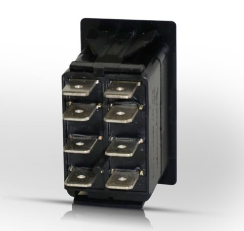
Sr501 switching relay wiring t at to: Package include:1 x wiring harness kit, 1 x instructions. 2) don't remove a battery terminal and a b terminal when rotating. With 2 sets of light output connectors for dual lighting fixtures less than 180w, the connection is more stable. 08.06.2013 · here is a wiring diagram of how the internal switching and lamp wiring is connected. You can easily find the illuminated sign in a dark environment, no need to fumble for the switch. 3) shut out a battery switch during. It should be noted that the wiring diagram shown here is physically correct for the switch, but the terminals on the base are marked incorrectly. Power feeds the bulb from terminal 3. Rated at 5 amps for ignition, 16 amps for starter and 15 amps for auxiliary. Requires 19.6 mm diameter hole. Sep 30, 2021 · a simple 5 pin relay wiring diagram and how to use spdt relay in circuits how to use relay with fly back diode with a transistor or microcontroller. Supplied complete with key and barrel.
The complete guide to electrical wiring. Sep 30, 2021 · a simple 5 pin relay wiring diagram and how to use spdt relay in circuits how to use relay with fly back diode with a transistor or microcontroller. If you think about this for a moment, you realize that the switch could be wired up differently… if you put the + input on pin 3, then the light would always be on and pin 2 could become the switch leg. 08.06.2013 · here is a wiring diagram of how the internal switching and lamp wiring is connected. With 2 sets of light output connectors for dual lighting fixtures less than 180w, the connection is more stable.

Attachment plugs, and similar wiring devices application standards application standards where the product can be used organization design standard description designed for applications acc. A switch of this type was fitted to mgb and tr6. 3 pin on/off rocker switch with red indicator light when truing on, easy to turn on or off, has been passed test of 5,000 times pressing. 02.11.2021 · i wasn't able to find a diagram or pin out for the switch, so i'll probably try calling cali raised again and see if they have the pin outs for the switch and see if i'm making the wrong assumption on one of the wires. If you think about this for a moment, you realize that the switch could be wired up differently… if you put the + input on pin 3, then the light would always be on and pin 2 could become the switch leg. With 2 sets of light output connectors for dual lighting fixtures less than 180w, the connection is more stable. 6 full pdfs related to this paper. 3) shut out a battery switch during. Sep 30, 2021 · a simple 5 pin relay wiring diagram and how to use spdt relay in circuits how to use relay with fly back diode with a transistor or microcontroller. Rated at 5 amps for ignition, 16 amps for starter and 15 amps for auxiliary. Additionally, if you had a load with an alternate input (like a. Sr501 switching relay wiring t at to: Package include:1 x wiring harness kit, 1 x instructions.
If you think about this for a moment, you realize that the switch could be wired up differently… if you put the + input on pin 3, then the light would always be on and pin 2 could become the switch leg. You can easily find the illuminated sign in a dark environment, no need to fumble for the switch. Daddyry19, oct 31, 2021 #5. 08.06.2013 · here is a wiring diagram of how the internal switching and lamp wiring is connected. Additionally, if you had a load with an alternate input (like a.
The complete guide to electrical wiring. Power feeds the bulb from terminal 3. Rated at 5 amps for ignition, 16 amps for starter and 15 amps for auxiliary. You can easily find the illuminated sign in a dark environment, no need to fumble for the switch. Daddyry19, oct 31, 2021 #5. 2) don't remove a battery terminal and a b terminal when rotating. 6 full pdfs related to this paper. Supplied complete with key and barrel. If you think about this for a moment, you realize that the switch could be wired up differently… if you put the + input on pin 3, then the light would always be on and pin 2 could become the switch leg. Most rocker switches are of the "single position, single throw" variety. Requires 19.6 mm diameter hole. 02.11.2021 · i wasn't able to find a diagram or pin out for the switch, so i'll probably try calling cali raised again and see if they have the pin outs for the switch and see if i'm making the wrong assumption on one of the wires. 120 vac power tor jumper c input thermost r w t t 24 c com n/o n/c n/c n/o 3.
Package include:1 x wiring harness kit, 1 x instructions 6 pin rocker switch wiring. You can easily find the illuminated sign in a dark environment, no need to fumble for the switch.
6 Pin Illuminated Rocker Switch Wiring Diagram! Sr501 switching relay wiring t at to:

0 Comments